Accurately measure height with microscope
As the subject implies this post describes a way to measure the height of an object using the motorized microscope. The whole trick is to take many incremental pictures of an object (and background as a reference) from different heights and analyze how sharp each frame is. Some interesting hardware is needed, but nothing that you might call fancy these days.
Setup
As I already had C1 camera, occasionally used small CNC and a microscope lens only lens and LED ring mount brackets had to be made. That was quick modeling with Fusion360. Started overnight SLA 3D print job and next day parts came out just perfect. 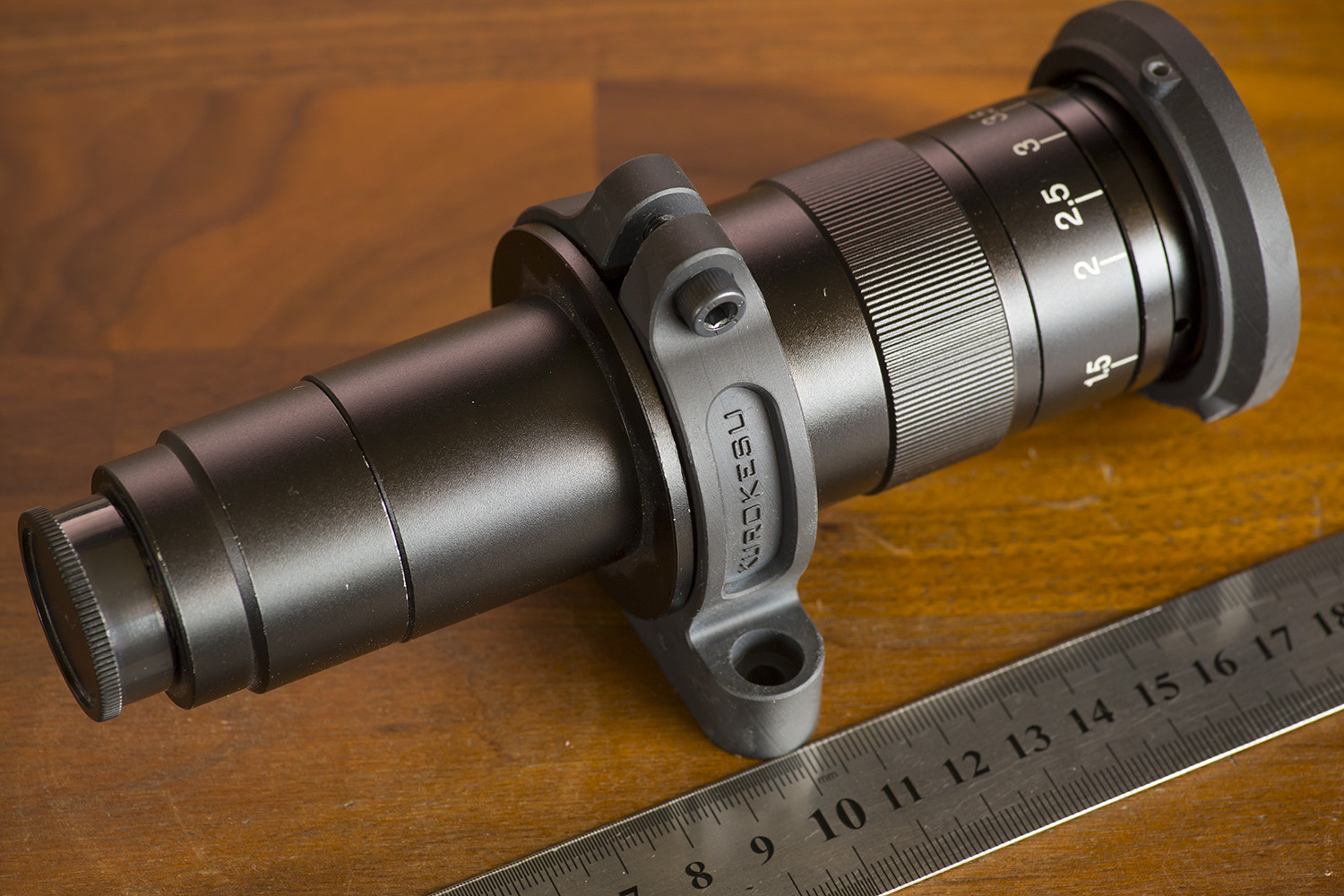
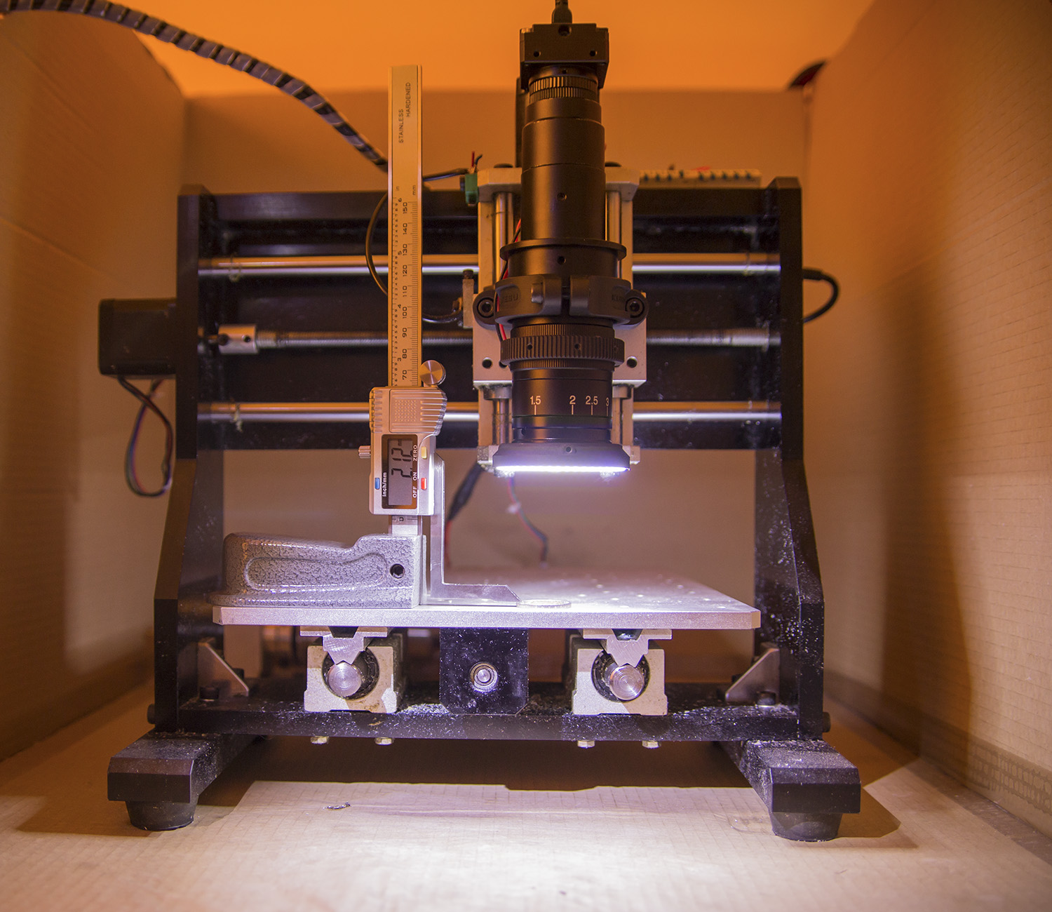
Mounted lens on motorized translation platform and gave it a spin. Worked on a first attempt. One minor issue – did not check Z travel and microscope working distance before installing and had to extend lens from a bracket. Only small parts fit in this rig in this present arrangement, but it is fine for now.
 Let’s roll and take a few hundred pictures of a coin at 0.01mm increments.
 As it usually happens for quick projects Python code is quick and dirty so I will describe base functionality instead of providing source code.
Motion control
In order to control motion platform, I use open GRBL controller. For example, to move Z axis by 1.1mm send a command like “G1 X0 Y0 Z1.1 F600” to the serial port. After each complete step new picture is taken. The whole process is repeated until full defined range is covered.
Computer vision
Vision part is also pretty simple (see simillar technique used to auto-focus for motorized lens). OpenCV captures frames when instructed and saves them to disk for later analysis. Locking exposure and white balance usually helps to get more stable results. Sharpness evaluation is done by calling Laplacian transformation on each frame – it gives the numerical evaluation.
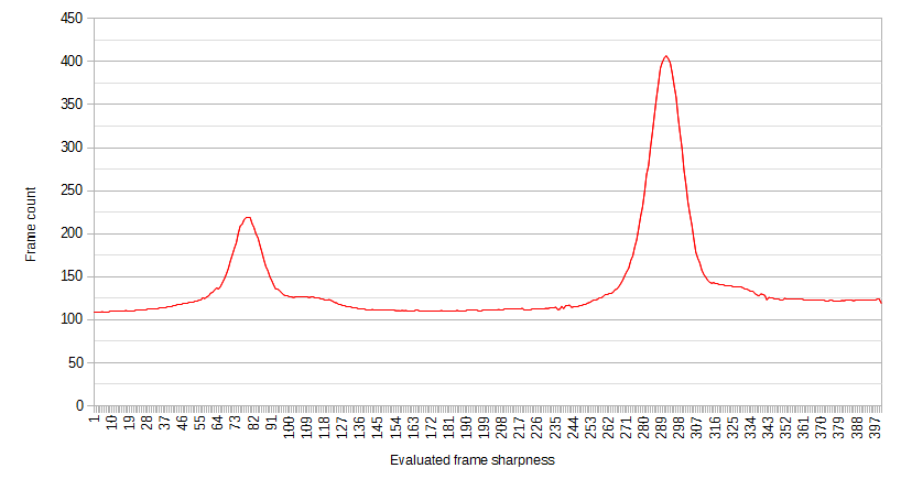
After analyzing all pictures and drawing calculated sharpness values on a chart we see two distinct peaks at position 78 and 290. Our Z axis step was 0.01mm, so quick math shows (290-78)*0.01 = 2.12mm. Actual measurement with height gauge and calipers was 2.12mm and Wikipedia says it is 2.20mm. That is close enough, I can write-off 0.07mm to natural wear and tear of the specific coin.
Conclusion
This is a very specific and interesting way to measure things that can not be touched or sealed inside a transparent container. There are limitations though – surfaces should be parallel and perpendicular to optical axis. Also, surfaces should have some texture in order to distinguish between sharp and blurry picture. Quick setup provided a possibility to measure pretty accurately, but repeatability and real-world performance is due to be tested with calibrated thickness gauges. Expected resolution according to Nyquist Theorem should be at least twice smaller than needed resolution. So for our example, we can say that measured distance is 2.12±0.01mm.