Measure linear rail quality with camera and excel
No matter how precise and rigid your mechanical system is, it will always have some imperfections. These imperfections can be measured and described. If measurements show opposite it means your measurement tools are not precise enough or you are doing it wrong.
There are a lot of expensive and highly specialized tools to measure every conceivable mechanical property, but this time let’s do some experiments with an unusual instrument like a camera and computer vision tool called visual odometry (just like an advanced optical computer mouse). It does not require precision reference plates or dial indicators and lets you measure sub-micron scale deflection on the bench.
Measurement
Used instruments and tools:
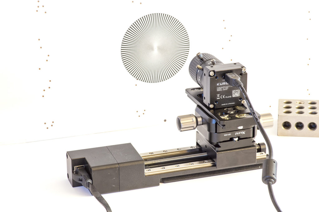
- Kurokesu C1 PRO camera with 2.8-12mm lens
- LSA1 linear slider from new motion devices
- Some mount plates and adapters
Quick math – view from a camera across the horizontal axis is about 70mm divided by 1920 pixels gives us resolution roughly 36.5μm per pixel. Keep this in mind. Keep in mind that a larger magnification lens will give more resolution but errors also will be larger.
After everything is mounted lets record a short clip. Motion can be initiated from a terminal program by issuing g-code string:
G1 X70 F20This will instruct GRBL firmware running on the SCE2-M controller to move X-axis motor 70mm at speed of 20mm/min.
Save the video and start motion analysis with a long-forgotten program VirtualDub + Deshaker plugin.
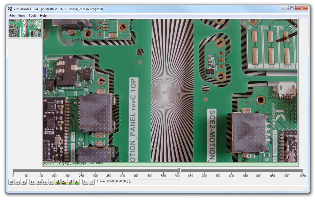
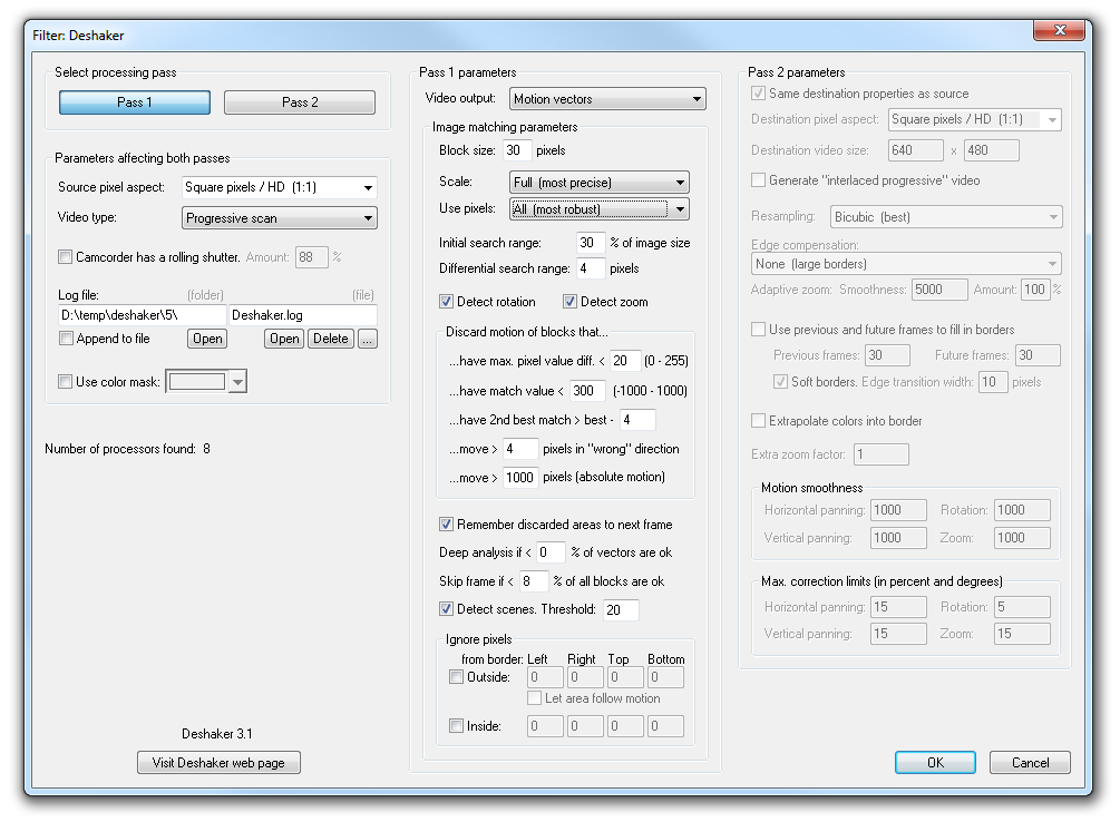
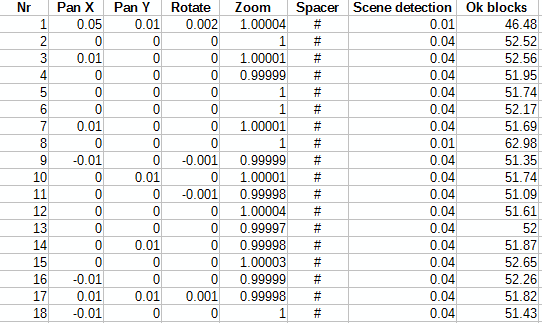
Run analysis and as a result, we will have a nice table with odometry data: Pan in X and Y axis, Rotation, zoom, and a few other parameters. Deshaker plugin saves file Deshaker.log for the second operation, but data is tab-separated and can be opened by a favorite spreadsheet program. It looks like this.
Graphs and results
The camera can be mounted parallel to each linear stage axis X, Y, or Z. Good thing is that absolute precision is not needed, alignment by eye is quite enough.
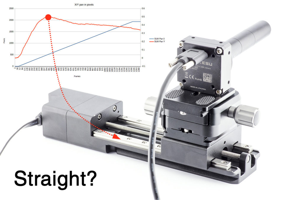
Here is an example graph of data received from the camera X-axis aligned with the linear stage.
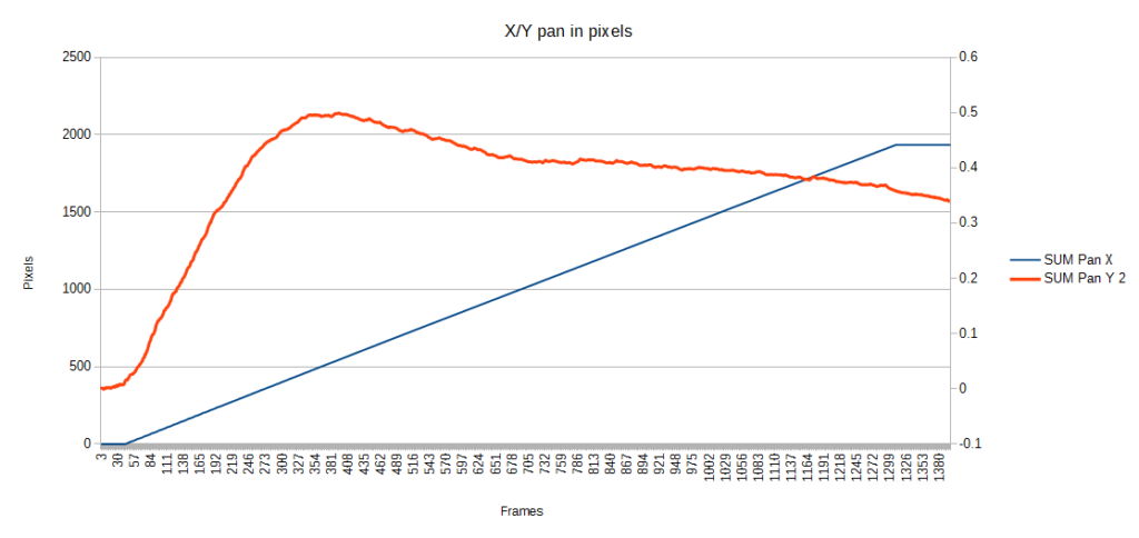
Let’s run quick sanity check math. X axis traveled 1934.3 pixels. Multiply by 36.5μm gives travel distance of 70.52mm. Which is close enough considering rough camera view area estimation.
It was not our goal to measure absolute precision, nonlinearity was parameter of interest. And orange graph shows this nicely. Other axis can be measured by mounting camera at different angle.
If camera is mounted collinear with linear guide X and Y axes as well as rotation will be measured at the same time, but keep in mind short camera depth of field. Limit motion range or it will influence feature detection quality.
Experiment notes and issues
The method described above lets anyone without any programming skills get hands-on visual odometry and evaluate their own CNC machine or 3D printer. However deshaker tool is not designed for this task as algorithm accumulates errors and absolute measurements are not possible.
- Measurement errors will accumulate, thus absolute measurements are not possible
- No way to estimate error magnitude
- More advanced tracking algorithms should be used, so off the shelf tools will not do the trick and programming skills will be need
- The carriage can have 6 degrees of freedom. Analysis from a single camera mounted on a moving platform can be complicated. On the other hand, if the motion scale is minute most likely mechanical system moves straight.